Fast Holographic-like Stereograms Display using
Shell Rendering and a Holographic Screen
Candido F. X. de Mendonça a,
Alexandre X. Falcão a
Cesar A. Vannini b, José
J. Lunazzi c
a Institute of Computing, State University
of Campinas, Campinas, SP, Brazil
b Math and Natural Sciences Center, Sacred
Heart College, Bauru, SP, Brazil
c Institute of Optics, State University of
Campinas, Campinas, SP, Brazil
Send correspondence to C.F.X.M., E-mail: xavier @ dcc.unicamp.br,
Telephone: +55(19)7885875, FAX +55(19)7885847
Background:
Display systems based on computer graphics techniques usually create 2.5D image display on a 2D screen. To obtain 3D image display, a system has to exploit some depth cues, such as horizontal and binocular parallaxes, that can only be represented in a 3D space. This type of system is divided in two major paradigms: Stereography (that makes use of stereo parallax) and Holography (that makes use of all depth cues). Stereography consists of giving to each eye a different view of the scene. A drawback in stereography is the use of auxiliary devices or viewing tricks (e.g, polarized glasses, virtual reality helmet, and divergent viewing). In some cases, such as in Virtual Reality, a considerable amount of computational resources is also required on detecting and redrawing scenes in the auxiliary devices for every new location of the observer. Holography consists of a process to register three-dimensional information of one object. Traditional holography makes use of hardcopy holograms to register the 3D information of objects as stereograms. This information is retrieved for display by illuminating the hologram with a reference light beam. Recently, holographic-like stereograms can be virtually created and stored by a computer and subsequently displayed on a holographic screen (i.e. a transparent film with grating and focusing optical properties, see [1]). The main advantage of this system over the others is that it requires less computational effort to generate and display 3D images. This technique is called holoprojection.
Motivation and Research Aims:
Our motivation for this work stems at the numerous applications that can be developed by using holoprojection to provide real 3D visualization.
In holoprojection, our aims of research are:
What is it all about?
We describe the incremental improvement of the research
over holoprojection that has resulted in two previous versions of Holoprojectors
and a new version that is introduced in this work. We purpose:
We also demonstrate the new system using medical image
data.
First Holoprojector:
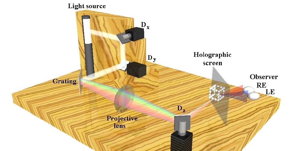
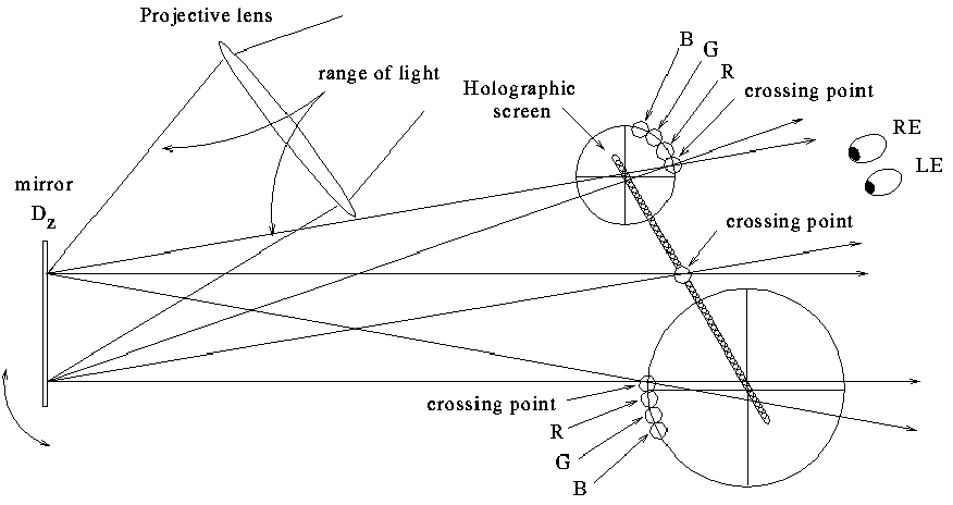
The first holoprojector [2] consists of an opto-mechanical system with a white light source, three mirrors connected to step motors (Dx, Dy and Dz), a reflective diffraction grating, a projective lens and a holographic screen (see Figure 1). The mirrors Dx and Dy place the beam of light in different x and y locations onto the diffraction grating. Due to the physics of the diffraction grating, the white beam of light is divided into two beams of light. The first beam of light, which carries on most of the brightness, is disregarded. The second beam of light is a spectral range of light. This range of light is wider as farther the grating is from the projective lens, since the origin of the range of light is the place where the white beam of light hits the diffraction grating. The range of light crosses the projective lens, and due to the convergence property of the lens, the mirror Dz positions the crossing point towards the holographic screen. Then the observer looking at the holographic screen can perceive the depth of the voxel formed by the crossing point (see Figure 2, where RE = right eye and LE = left eye). Thus, the set of voxels formed by all combination of movements of the mirrors Dx and Dy form a plane (or almost a plane) of voxels. The mirror Dz will place this plane of voxels towards the holographic screen in different positions forming a displaying volume. The observer sees a moving point of light that draws objects very precisely as, for example, the edges of a cube in real 3D volume.
First Holoprojector: Schema
FIGURE 1
Depth Encoding Process:
Second Holoprojector:
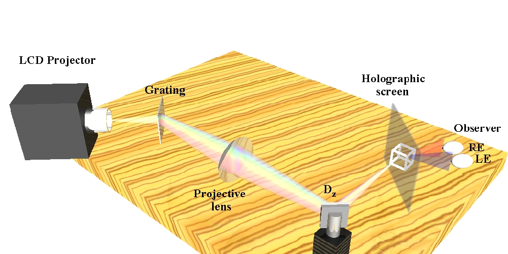
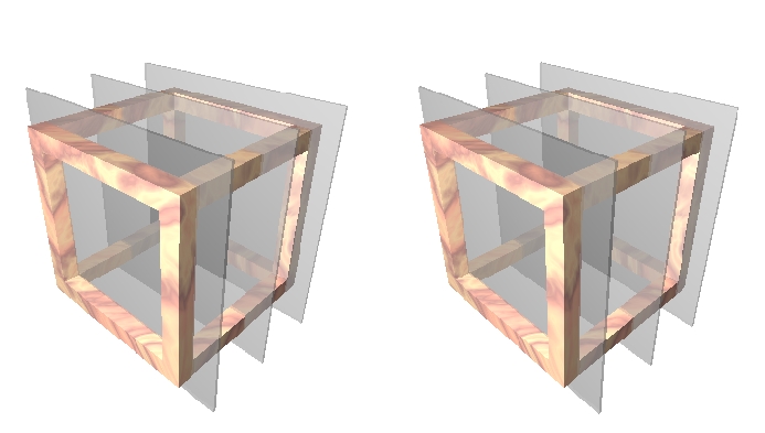
In the second Holoprojector [3], the mirrors Dx and Dy are eliminated from the set, and a LCD projector (see Figure 3) replaces the light source. As the whole plane can be displayed at a time, the scene must be sliced in an array of consecutive planes transversally positioned through the holographic screen by the mirror Dz. The reflective diffraction grating is replaced by a transparent diffraction grating and the rest of the system remains the same. The images are then projected rather than being mapped by the movement of the mirrors. The scene shown by this system is generated by a ray-tracing program modified to allow the slicing process. The slicing process depicts a virtual version of how a baker slices a loaf of bread. Figure 4 displays a stereo pair of cutting planes of the slicing process of a scene. Each slice is displayed as a two-dimensional textured object; the set of two-dimensional slices builds a volume display.
Second Holoprojector: Schema
Slicing Process:
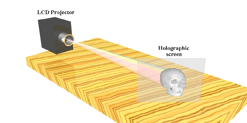
Third Holoprojector:
In the third Holoprojector, we eliminate the diffraction grating, the objective lens and the oscillating mirror Dz. It consists simply of a LCD projector and a holographic screen (see Figure 5). To display a 3D object in this system, we first create an ordered sequence of n views of the object with discrete horizontal parallax and select an ordered sequence of n hues in the spectrum of visible pure colors. To each view we assign a different hue following the order of the sequences. Thus we have coded n views forming a frame of holographic-like stereogram. An animation can be created as a sequence of frames like this. By projecting the holographic-like stereograms onto the holographic screen, we obtain n views of the object per frame and the observer can see 3D images of the object per frame with discrete horizontal parallax. As the LCD projector is based on RGB colors, we have used just three pure colors Red, Green and Blue at the moment.
Holoprojector 3.0: Schema
3D Visualization: Medical Imaging Applications
The main point in this work is to demonstrate that the
third version of the Holoprojector (Figure 5) can be used in medical imaging
applications to provide fast 3D image display of human internal structures.
In this case, the requirement for a fast rendering technique is crucial,
since each holographic frame corresponds to three (in the case of three
pure colors) rendered views of the structure with discrete horizontal parallax.
Shell rendering, proposed by Udupa and Odhner [4], can be placed as one
of the fastest rendering techniques developed so far. In this work, we
adopted a particular implementation of the shell data structure for surface
rendering.
In medical imaging, a 3D object may be represented by
a set of voxels in the vicinity of its boundary. A shell consists of this
set of voxels together with a number of attributes associated with the
voxels in this set. The shell is stored in a special data structure that
allows random access to the voxels and their attributes. Shell rendering
is a very fast voxels projection technique that creates 2.5D views of the
object from the shell data structure. Thus, for any given location of the
observer, we code three views of the object (i.e. Red, Green and Blue)
with discrete horizontal parallax and use the third Holoprojector to display
this 3D image on our holographic screen.
Experiments and Results:
Our prototype display system (third Holoprojector) consists of a NTSC LCD 60Hz projector and a holographic screen. This holographic screen can show any number of views within about 6 degrees of horizontal parallax. We have chosen an entire CT skull, where the boundary is represented by 1,500,000 voxels, and a SUN Sparc 4 64MB RAM for our experiments. Since typical projectors support three colors, we have coded three views (with resolution 320x320 pixels) of the skull with horizontal parallax to form a holographic-like stereogram (see Figure 6). This task takes about 1 second using shell rendering. The holographic-like stereogram is subsequently displayed free of flicking onto the holographic screen by the NTSC projector. Therefore, the whole system allows real 3D interactive visualization without auxiliary devices or viewing tricks.
Viewing Encoding Process:
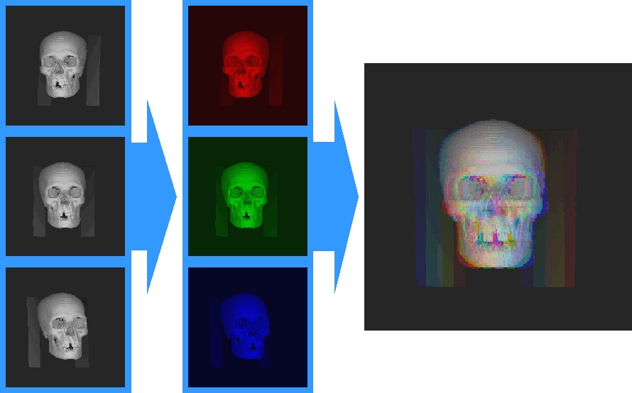
FIGURE 6
Concluding Remarks:
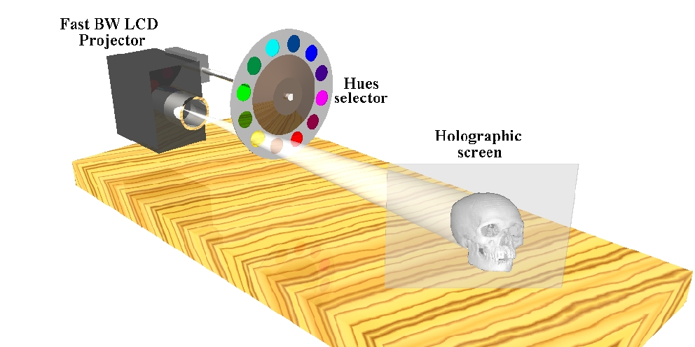
We have presented a new technique based on shell rendering, which can generate holographic-like stereograms from typical medical image data in real time. We have also presented a new 3D display system to visualize holographic-like stereograms on a holographic screen, without viewing tricks or auxiliary devices. Today, our system has some limitations: 6 degrees of horizontal parallax, the distance of the projection, the range distance of the observer and 3 coded views. The first three limitations can be relaxed on the building process of the screen and the number of coded views (discrete horizontal parallax) can be increased to 64 by using a gray LCD 2KHz projector, available today, and a 60Hz arrangement of 64 hue filters as shown in Figure 7. With this arrangement, we can display on our holographic screen 64 views of the object per frame with no flicking.
Holoprojector 4.0: Schema
References:
[1]. J. J. Lunazzi. New possibilities in the utilization
of holographic screen. Proc. of the SPIE meeting Electronic Imaging, conference
Practical Holography VI, San Jose-CA-USA, 9-14:289-293, February 1992.
[2]. J. J. Lunazzi and M. Diamand. 3D display system
based on holographic screen and microcomputer-driven galvanometers. Applied
Optics, 34(22):4697-4699, 1995, http://www.geocities.com/CapeCanaveral/Lab/6146/apopt95.pdf.
[3]. E. G. da Fonseca and P. L. de Geus and C. F. X.
de Mendonça N. and J. J. Lunazzi and E. Bertini. A Holographic Visualization
System: A Sequel. in Proc. of The XI International Symposium on Computer
Graphics, Image Processing and Vision, SIBGRAPI'98, pages 135-141, October
1998.
[4]. J. K. Udupa and D. Odhner. Shell Rendering. IEEE
Computer Graphics and Applications, 13(6):58-67, 1993.